TLS Instrumentation Control system includes two major parts: accelerator control system and beam diagnostic system. Control system adopt distributed hardware and two-level client/server infrastructure (as Fig. 1) to make expansion requirement more feasible. Besides, real-time multi-tasking software infrastructure provide friendly environment for system development (as Fig. 2). In upper client level, there are many various servers and platforms. Control servers would serve for application program, data storage and beam dynamic calculation/simulation; workstations would provide OPI interface, data input/output and GUI display. In lower level, it’s a hybrid system of VME crate based intelligent local controller (ILC) and EPICS (Experimental Physics and Industrial Control System) IOC (Input / Output Controller) which would be responsible for subsystem controls and monitoring. Client and IOCs would be connected with 100 M/1G/10G Ethernet for communication. All data from all ILC and EPICS IOC would synchronized updated at 10 Hz up to the database of the upper servers/platforms and accessible for diverse application program includes operator interface (OPI) of subsystem, functional OPI, startup/shutdown process, archive, alarm system, specific computer procedure, beam dynamic AP and etc.
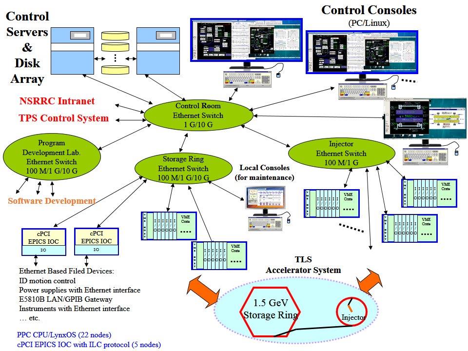
Figure 1、Hardware architecture of TLS control system
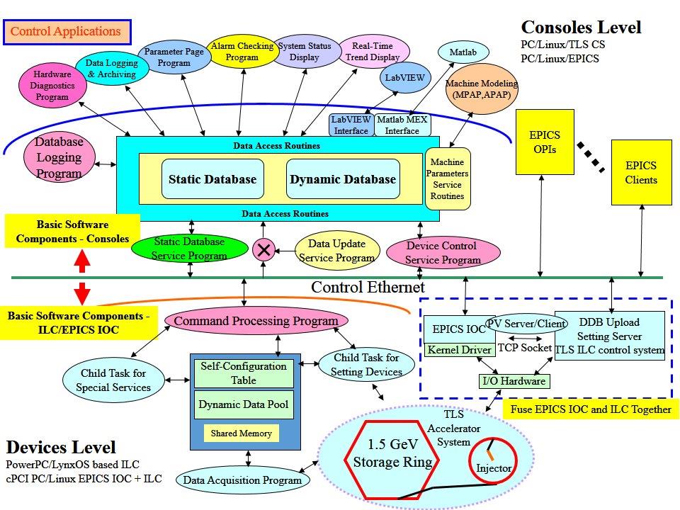
Figure 2、Software infrastructure of TLS control system
Beam diagnostic system is to see and listen what accelerators are function. It could provide various parameters of the electron beam for accelerator control, routine operation and beam physics study. It provide beam position/orbit, current, betatron and synchrotron frequency, bunch length, beam size and etc. which could infer machine parameters and beam stability. Orbit feedback system and bunch-by-bunch feedback system would ensure beam stability to provide high quality synchrotron radiation.
Figure 3 ~ Figure 10 show the TLS control hardware and GUI display. TLS instrumentation and control system have been operational for 25 years. It’s been updated for several times to catch up technology advanced and avoid obsolete of equipment. There are many efforts were done during last two decades, for example, it was decided to adopt EPICS system in 2010 and gradually replaced for old fashion platforms.

Figure 3、TLS transport line corrector power supply and control interface
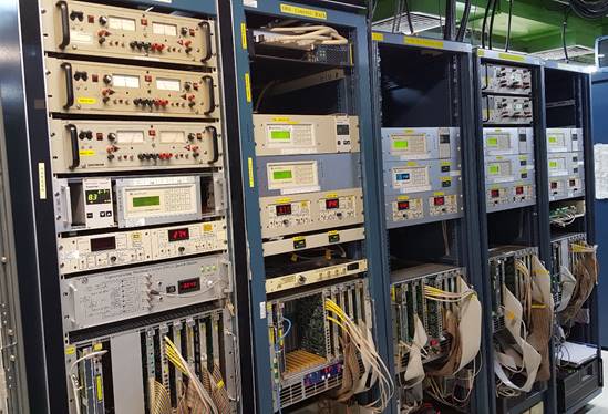
Figure 4、TLS control crate for superconducting insertion devices
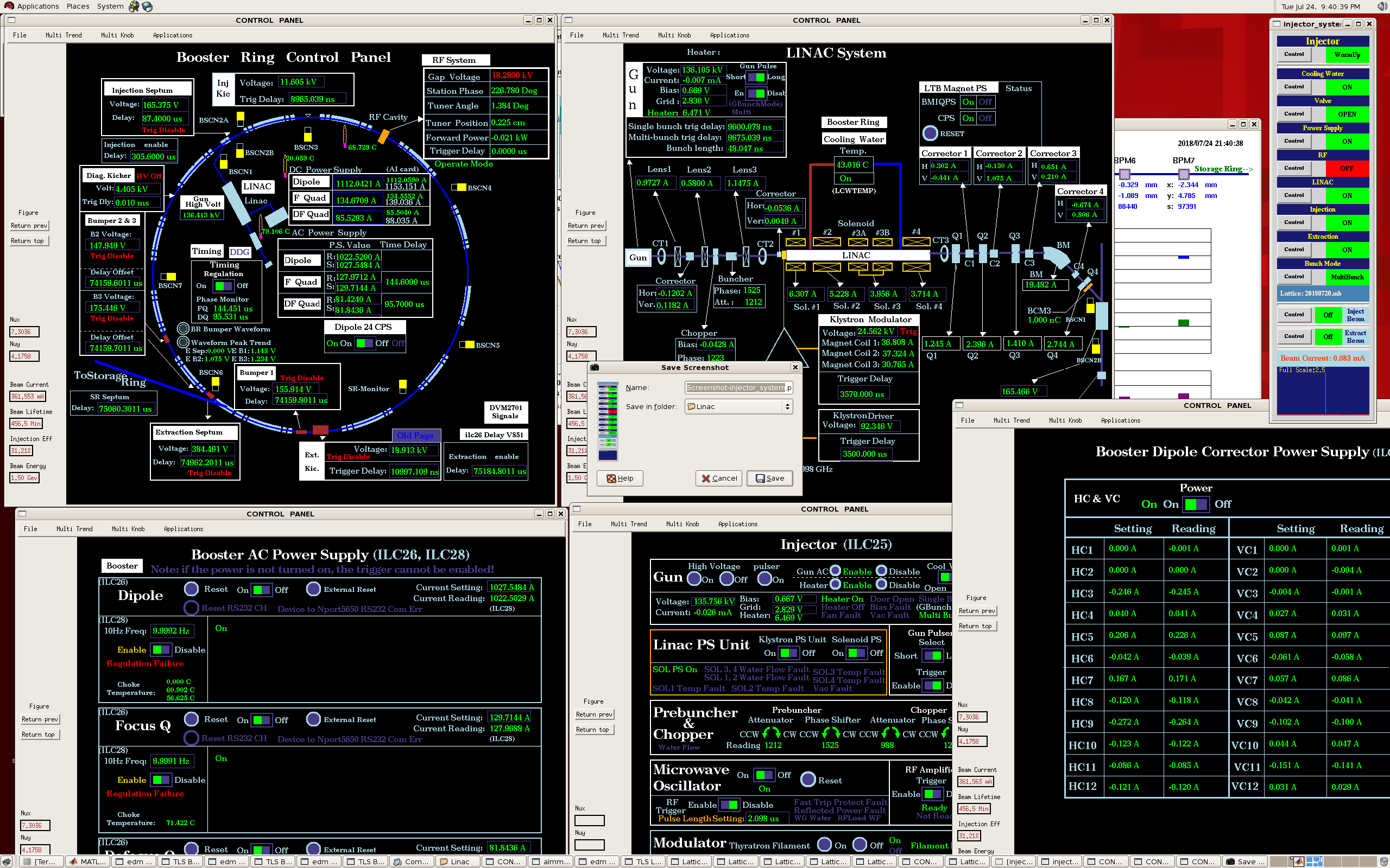
Figure 5、TLS Booster control GUIs to support operation
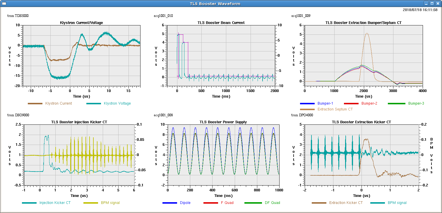
Figure 6、Waveforms acquired from the TLS booster to help operation conditions monitoring.
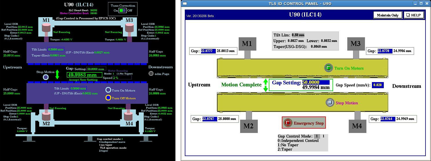
Figure 7、TLS U90 OPI: (a)Original OPI (b) EPICS OPI
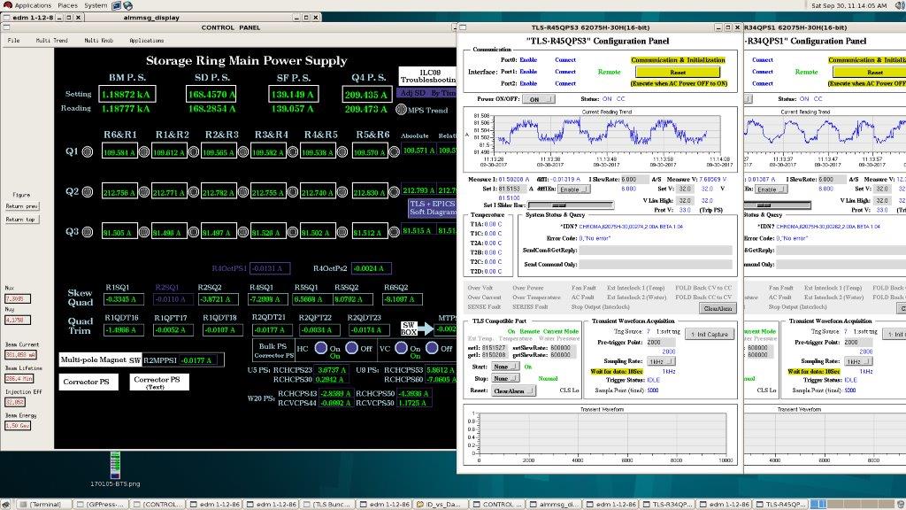
Figure 8、TLS Main power supply control/monitor GUI
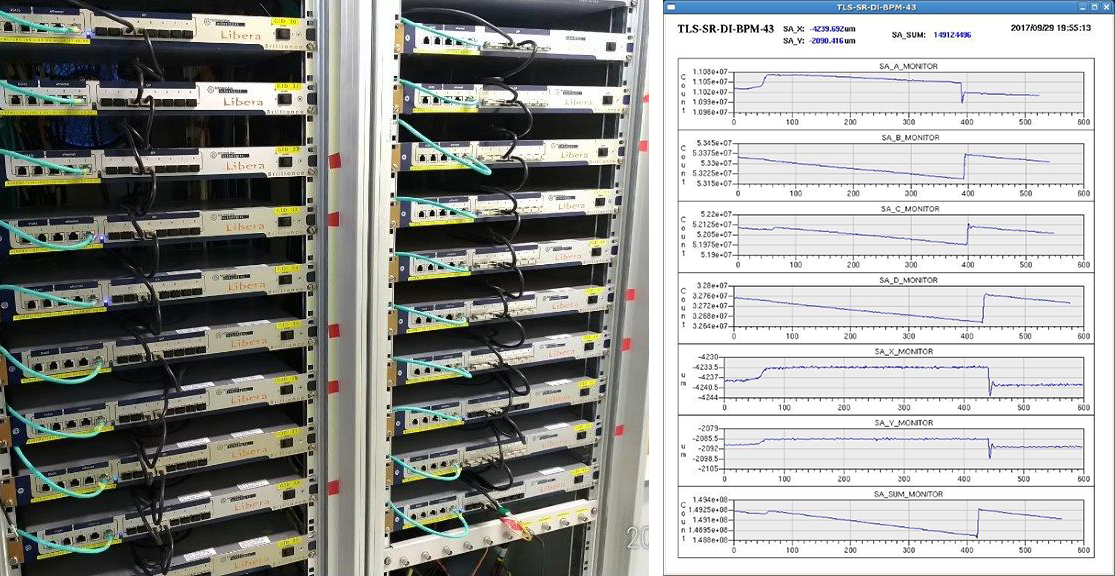
Figure 9、TLS beam position monitor electronics and the related device control GUI
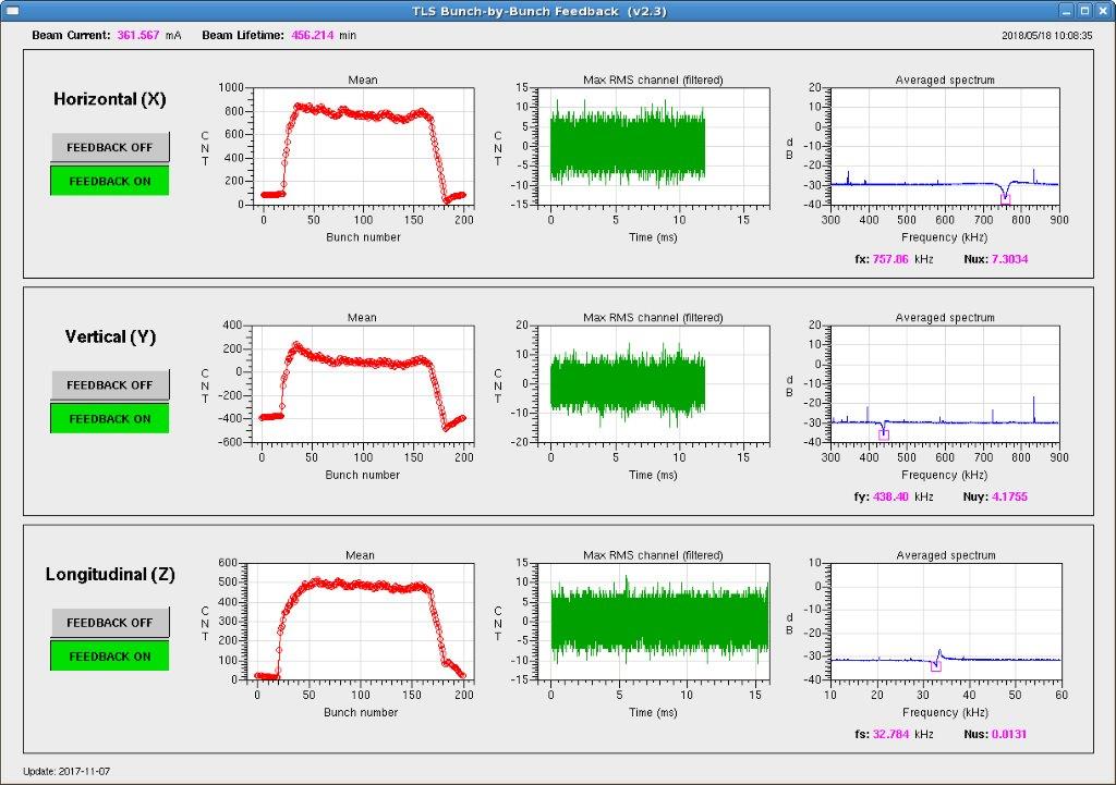
Figure 10、User interface of the TLS bunch-by-bunch feedback system
TPS Instrumentation Control system also includes two major parts: Accelerator Control system and Beam Diagnostic system. There are many servers for various function and 300 Input / Output Controller (IOC) in control system as Figure 11. Control software adopts EPICS - Experimental Physics and Industrial Control System framework. The infrastructure is shown as Figure 12. Servers would be served for file storage, database, alarm and etc. as Figure 13. Besides, there are many consoles for easy operation as Figure 13. The control main page as Figure 14 could be provided for clicking to subsystem control.
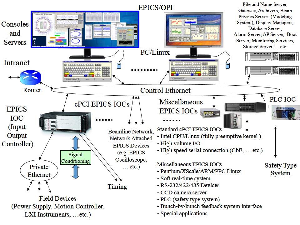
Figure 11、Hardware architecture for TPScontrol system
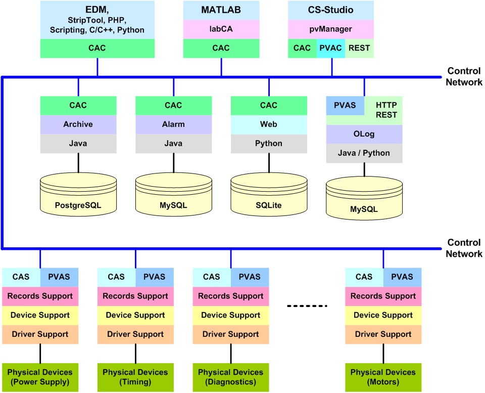
Figure 12、software infrastructure for TPS control system
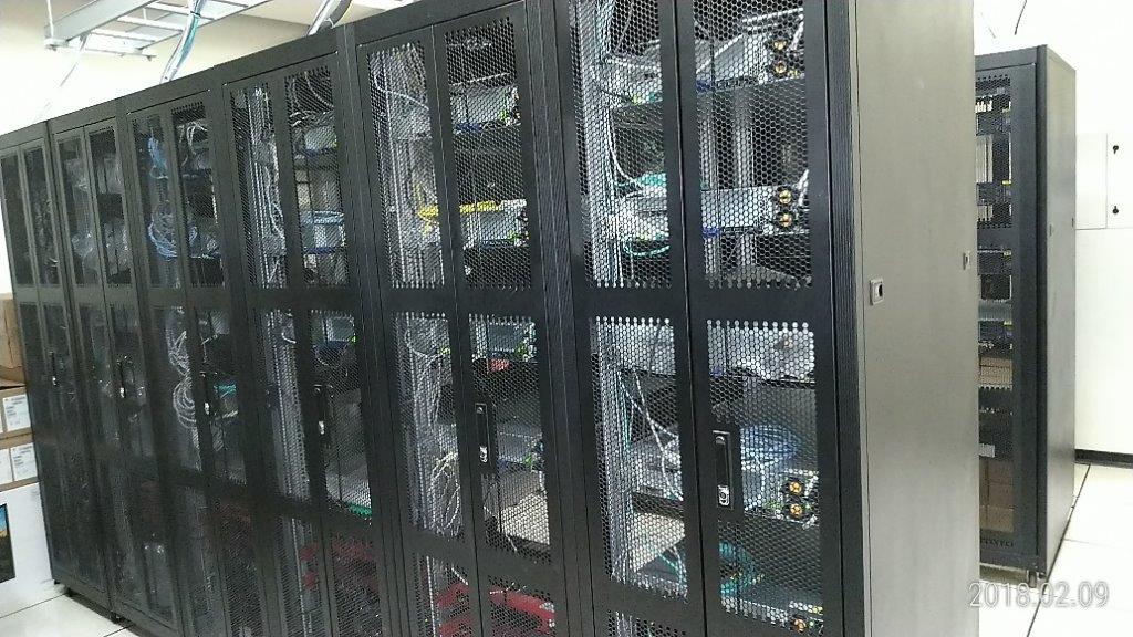
Figure 13、TPS computer servers in server room
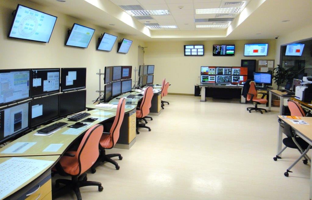
Figure 14、TPS control consoles in control room
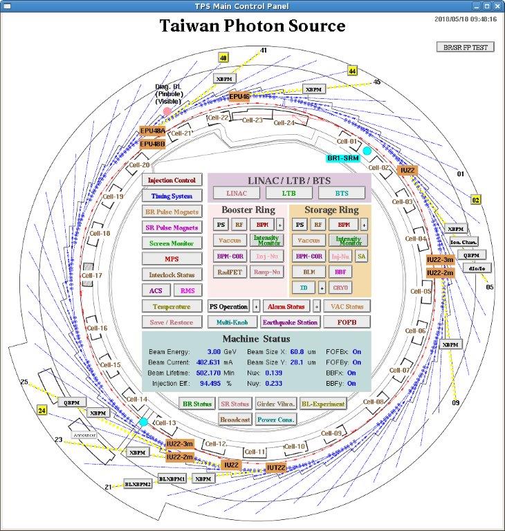
Figure 15、TPS control main page
Accerelator control system includes subsystems: Timing system could distribute control signal all around the accerelator for timing control; power supply controller could connect thousands of magnet power supply; iterlock system provide saftey for radiation protection and beamline emergency stop to ensure machine and personal saftey; insertion device control system could provide precise remote control to satisfy various operation requirements from end-station users as Figure 16.
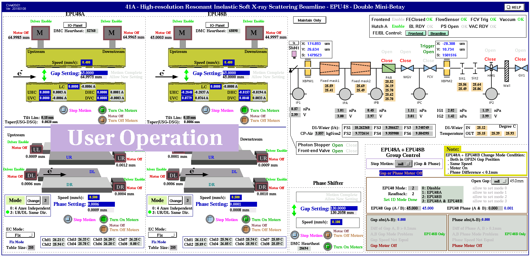
Figure 16、EPU48 control GUI
Similar with TLS, TPS beam diagnostic system also provide various parameters of the electron beam such as beam position/orbit, current, betatron and synchrotron frequency, bunch length, beam size as Figure 17 and etc. It could infer machine parameters and beam stability. Combined with orbit feedback system and bunch-by-bunch feedback system, electron orbit could be stabilized and bunch instability could be suppressed to ensure beam stability and reliability which would provide high quality synchrotron radiation and meet requirement of users’ experiments. Furthermore, to quickly clarify the causes of beam trips, post-mortem diagnostic system is developed to collect and analyze all related data as shown in Figure 18. It contributes a lot for improving the machine reliability.
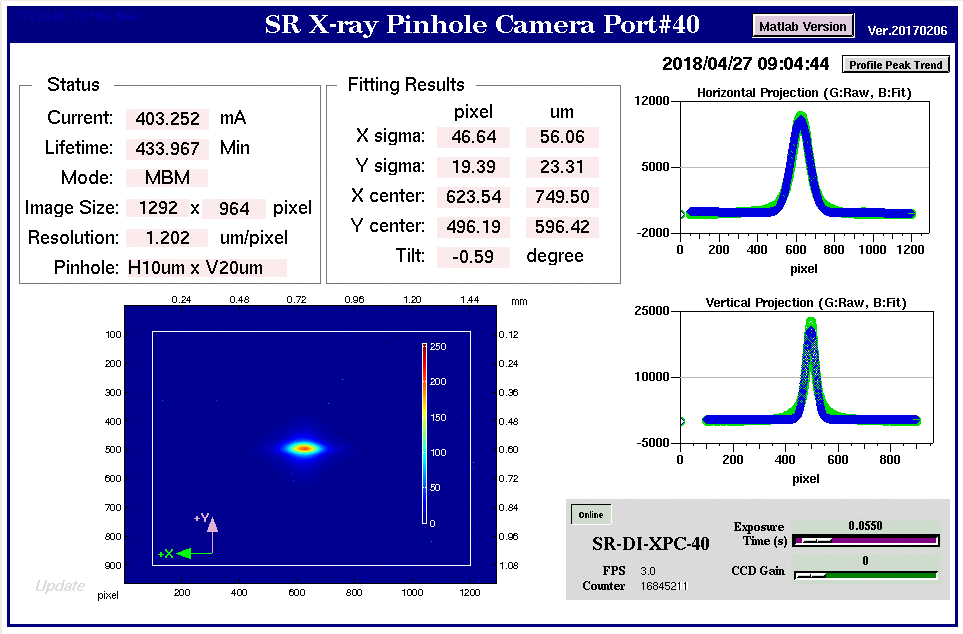
Figure 17、TPS beam size measurement
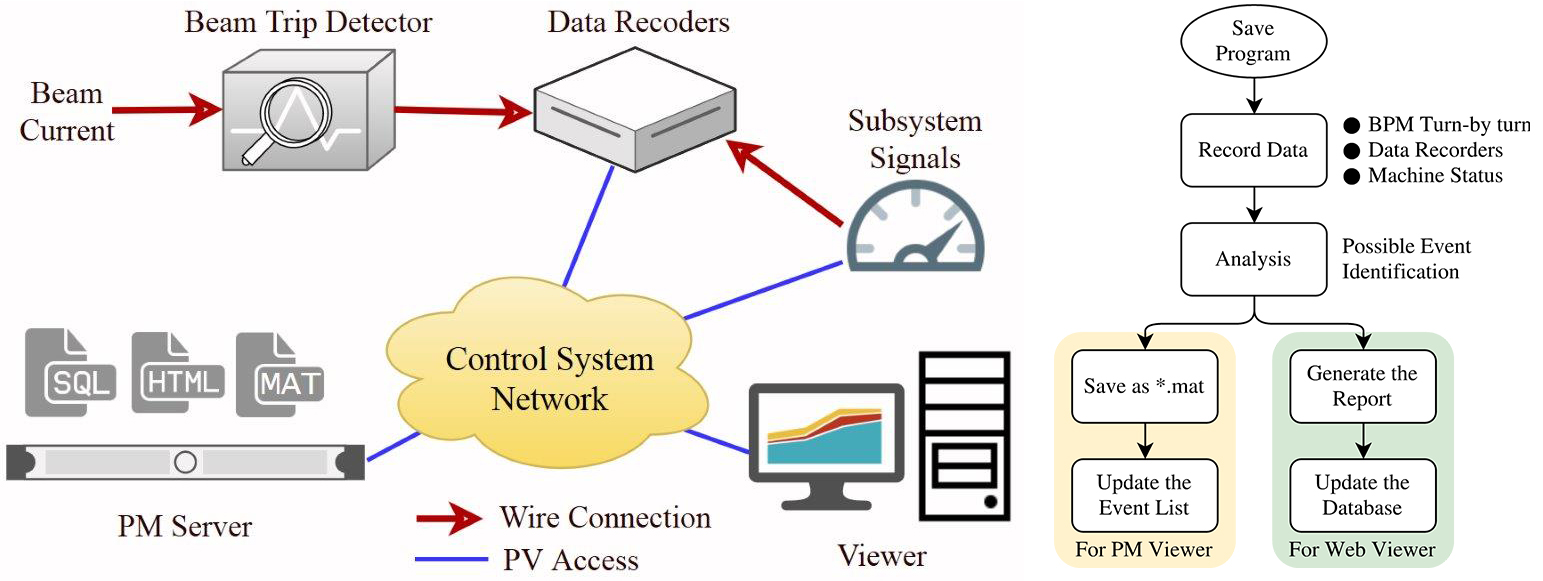
Figure 18 Post-mortem system quickly analyzes the causes of beam trip