Mission of Utility and Civil Group
The Utility and Civil Group is responsible for the daily maintenance of utility related and civil construction works as shown in Fig.1. These tasks include the cooling water system, the air conditioning system, the pneumatic system, the power system, the fire protection system, the exhaust system, the civil construction, the instrumentation control system and the photovoltaic system. It provides an infrastructure to serve TLS and TPS accelerators and their facilities for maintaining a stable and reliable operation. A high precision control mechanism and management system were also developed in order to meet the requirement demanded by present accelerator facilities.
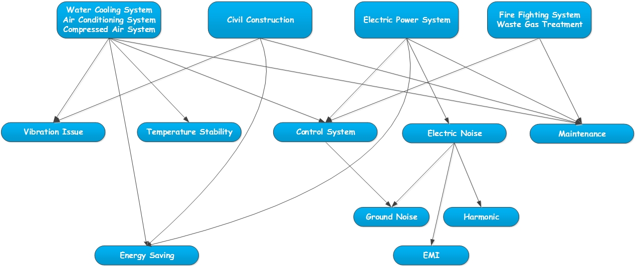
Figure 1: Work-breakdown structure of the Utility and Civil Group.
Cooling Water System
The heat sources are mainly from the sensible heat generated by accelerators and their peripheral equipments and the latent heat generated due to the activity of personnel. A simple heat transfer diagram in our facility is shown in Fig. 2. The heat generated by the accelerator and its related device is carried away mainly by the de-ionized cooling water (primary heat exchange), then, by a secondary heat exchange with the chilled water or the hot water system. Finally, the heat will be dissipated to the atmosphere through the cooling tower.
In summary, in the facility of synchrotron accelerator the cooling water system should include the de-ionized water system, the chilled water system, the cooling tower water system and the hot water system. Except the cooling tower water system, all other water systems are closed loop systems. The water in the close loop will return the water to the main equipment room to undergo heat exchange and water regeneration treatment. Then, the water will be sent through pumps to each subsystem. It provides the cooling for the accelerator and its peripherals and the air conditioning of buildings.
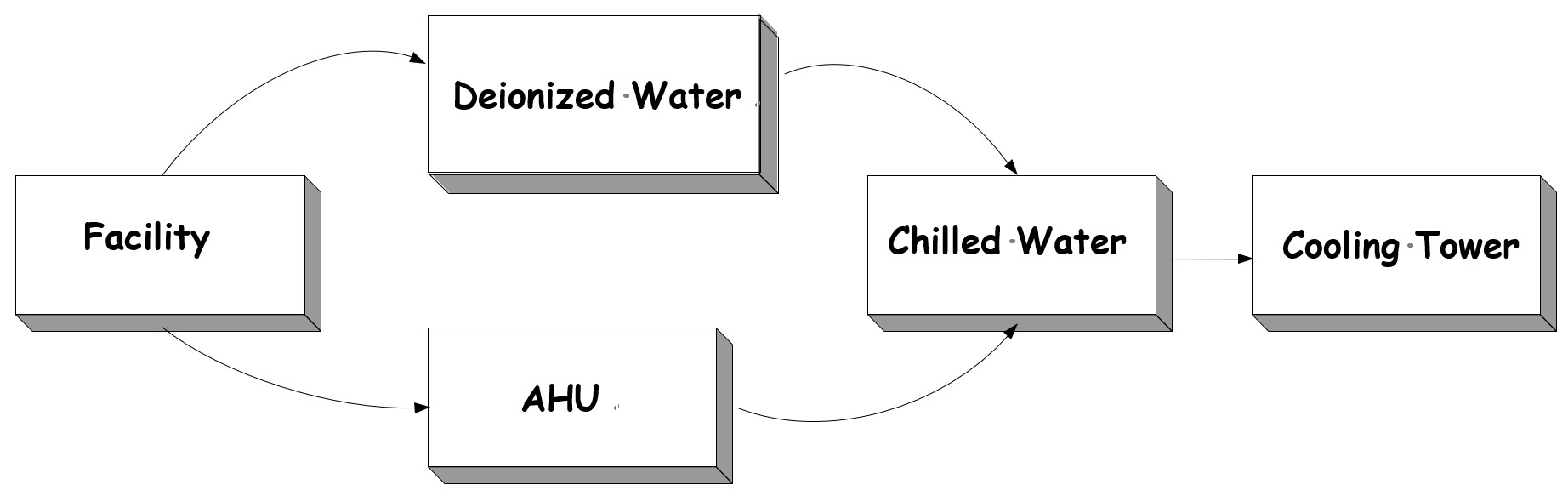
Figure 2: Schematic diagram of heat transfer.
In the synchrotron facility, water is used as major medium for cooling. The de-ionized water is used in the primary heat exchange for cooling of devices in the storage ring. There are 4 subsystems due to the diversity of equipments, which consists of the de-ionized water for Cu system, the de-ionized water for Al system, the de-ionized water for RF system, the de-ionized water for booster system and beam line systems. The de-ionized water for Cu system provides the cooling for magnets and magnet power supplies. The de-ionized water for Al system is for the cooling of storage ring vacuum chamber. The de-ionized water for RF system is for the RF related devices. The reason to use the 4 different de-ionized water systems is to prevent the corrosion due to the electric potential difference from the different metal activity between different equipments. And, it also more effective in maintain a stable pressure, flow rate and temperature.
In order to minimize the thermal deformation and higher stability of components of subsystems of TPS accelerator, the water pressure of the de-ionized water must be kept within 7.5±0.1 kg, and the water temperature must also be maintained within 25±0.01 oC. The schematic diagram for de-ionized water system is shown in Fig. 3. The green line is the de-ionized water. The higher temperature water after passing the components which has been cooled will pass the steam separator to separate the steam and water. Then, 5% of the returned water will enter the mixed bed exchanger to undergo water treatment and return back to the water return pipe. All the returned water will be pressurized by pump, so it can circulate in the pipe. Thereafter, the water will pass through two heat exchangers, one for cooling with 7.0 ℃ chilled water (blue color) and another for heating with 50 ℃ hot water (red color). Then, the water will flow to each subsystem again. When the water level is too low, the water can be replenished according to the water level gauge in the expansion tank. The replenished water comes from the reverse osmosis water storage tank and passes through regenerative pump, then, flows back to the return pipe. In order to achieve a higher precision temperature control, another mixed flow tank is added in to fine tune. After this improvement, the fluctuation of temperature can reach ±0.01 ℃. To those devices which require a high precision temperature control, this design can reduce the thermal disturbance to a minimum.
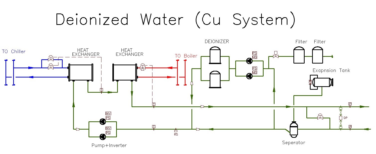
Figure 3: Schematic diagram for de-ionized water system
Also, the chilled water, the hot water and the cooling tower water are the medium for second and third heat exchange process, respectively. They must meet certain degree operation accuracy in order to optimize the control of de-ionized water. In our system, the demand for the water temperature is 7.0±0.2 ℃ for chilled water, 32±0.5 ℃ for water tower cooling and 50±0.3 ℃ for hot water, respectively.
Air Conditioning System
Beside the general type of air conditioning system used in NSRRC, a special air conditioning and temperature control technique was developed to meet the special environmental requirement for the accelerator operation requirement. This approach can enhance the stability of temperature variation.
Control of air conditional system
The central air conditioning system is the primary air conditioning system in NSRRC. The air handling units are used to regulate and circulate air. Fig. 4 shows a simple configuration of air circulation design. After the air returned from the supplied area and mixed with the outside air, it exchanges heat with the chilled water heat exchanger. In this stage, the chilled water control valve controls the heat exchange quantity. Then, the temperature of air will be cooled down to the setting temperature and the relative humidity approaches saturation. Thereafter, the air will perform heat exchange in the hot water heat exchanger before it enters the air condition supply area. The hot water control valve controls the quantity of heat added which enable the quality of air delivered attaining the preset temperature and humidity.
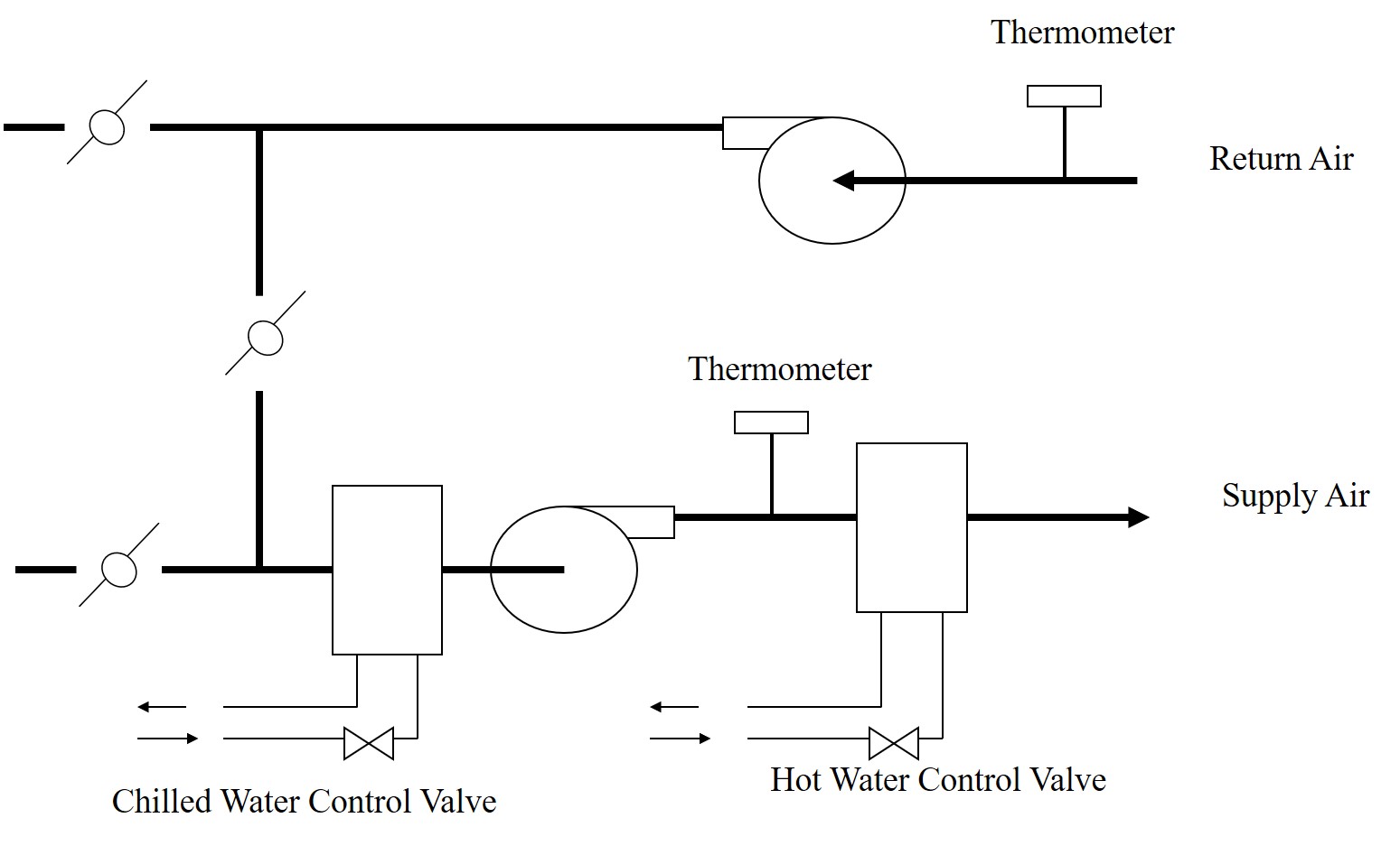
Figure 4 Schematic diagram of air conditioning system.
Temperature control in the accelerator tunnel
According to previous studies at NSRRC the temperature in the tunnel area of the storage ring is closely related to the stability of electron beam orbit. As the variance of temperature is larger than 0.3 oC, the position of electron beam will be disturbed. By providing sufficient cooling capacity to the tunnel area and deploying thermometer uniformly for monitoring, the air conditioning temperature can be measured precisely. Through the optimized control parameters, the variation of air temperature inside the storage ring tunnel can be regulated within ±0.1 ℃, Fig. 5.
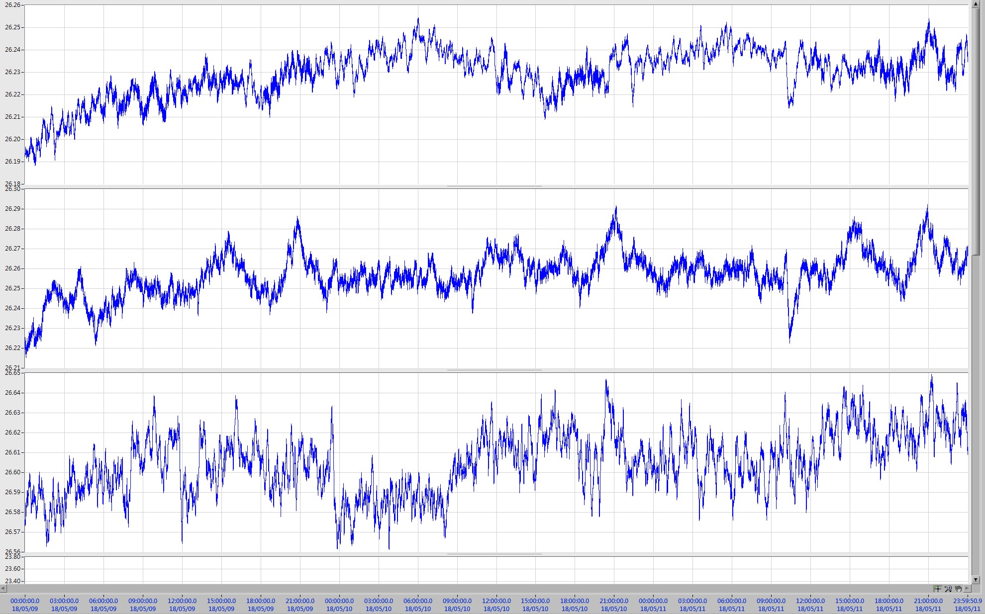
Figure 5: The temperature variation in each segment.
Local isolated temperature control
Beside the temperature control of whole storage ring tunnel area, mini environmental air conditioning systems are also installed for some important precision equipments, such as EPU insertion magnets, U5 insertion magnets and I/O monitoring system. It shows very effective. It uses the isolation material, such as plastic sheets, to isolate the equipment from outside. Also, cross flow fans were installed to distribute evenly the air flow and the temperature in this area, Fig. 6.
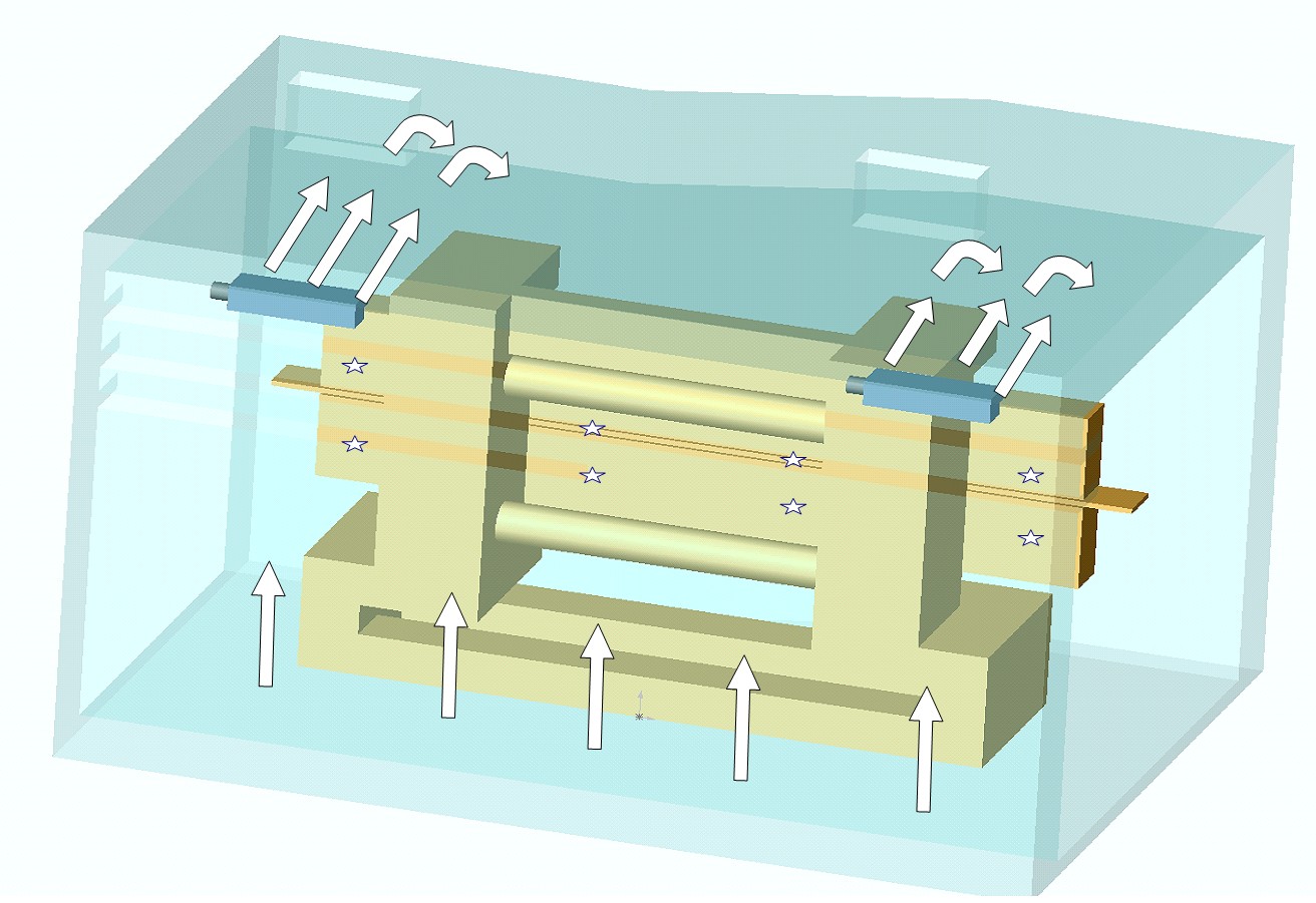
Figure 6: Diagram of the local isolated temperature control system.
Control System
Design and maintenance of monitoring system
There are various types of devices and equipments used by the Utility and Civil Group. Each system has its own specific communication protocol and graphic control format. It causes some difficulty in management and maintenance. An integrated monitoring and control system was developed by our group to consolidate these different control systems, Fig. 7. Besides retaining the original control architecture of each system, one more layer of management and data analysis was added. Our developed monitoring and control system has adopted the architecture of NI compactRIO, which meets the requirement for the high precision and fast data acquisition demanded by the advanced research.
Figure 7: Design and maintenance of monitoring and control system.
Research on high precision temperature control technique
In order to keep up with the rapid change of accelerator technique, the demand for cooling technique is more stringent. Our group used buffer tank, control valves, heat exchangers, and the optimized control algorithm to stabilize the de-ionized water temperature at ±0.01 ℃ and maintain the temperature at about ±0.02 ℃ at the air conditioner , Fig. 8.
Figure 8: Studies of high precision temperature control technique.
Intelligent energy saving measure
The de-ionized water and the air conditioning system are the main equipments to carry away the hot waste gas to the atmosphere. During the process of thermal transmission the efficiency of equipment and the management of energy saving have affected the power consumption of all facility. Thus, an intelligent energy saving measure was applied to the equipment. Moreover, these logical algorithm and management mechanisms relies on flexible monitoring and control technique, such as the run-around of air handling unit, the enthalpy control of outside air, the optimized operation efficiency, the control technique will all be applied to each control layer.
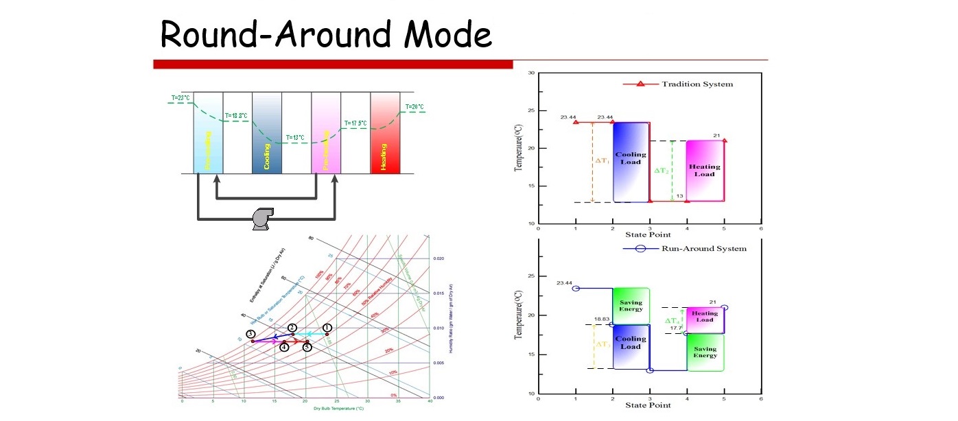
Figure 9: Schematic diagram of Run-Around mode.
Power System
Performance enhancement of electrical power system
A lot of efforts have been devoted to improve the reliability and the quality of NSRRC electrical power system in recent years. The improvements include the power factor correction, solving nuisance tripping of air circuit breakers, replacing old-type capacitor banks, installing automatic voltage regulators and designing multi-source backup system with automatic transfer switches, Fig. 10. All these improvement works are to ensure the reliable operation of NSRRC power system and to reduce the electrical power accidents during the normal operation. Further, it can also provide the convenience for the electrical power dispatching during the regular maintenance of power system.
Figure 10: The mutual backup system of emergency power.
Electrical power SCADA system
The use of power SCADA system provides the control and the information acquired from remote equipment, Fig. 11 and Fig. 12. It enhances the operator’s ability to manage the power system. Any faults occur in the system can give alarms to the operators, so they can analyze the causes of faults and take immediate measures to clear the faults and recover the system to normal. From analyzing the accumulated long period of data, the conditions of devices in operation can be understood. Thus, the problematic devices can be discovered early and replaced or repaired beforehand to avoid or minimize the false operation of power system. In the near future, many more devices are planned to be included in the power SCADA system to further enhance its function.
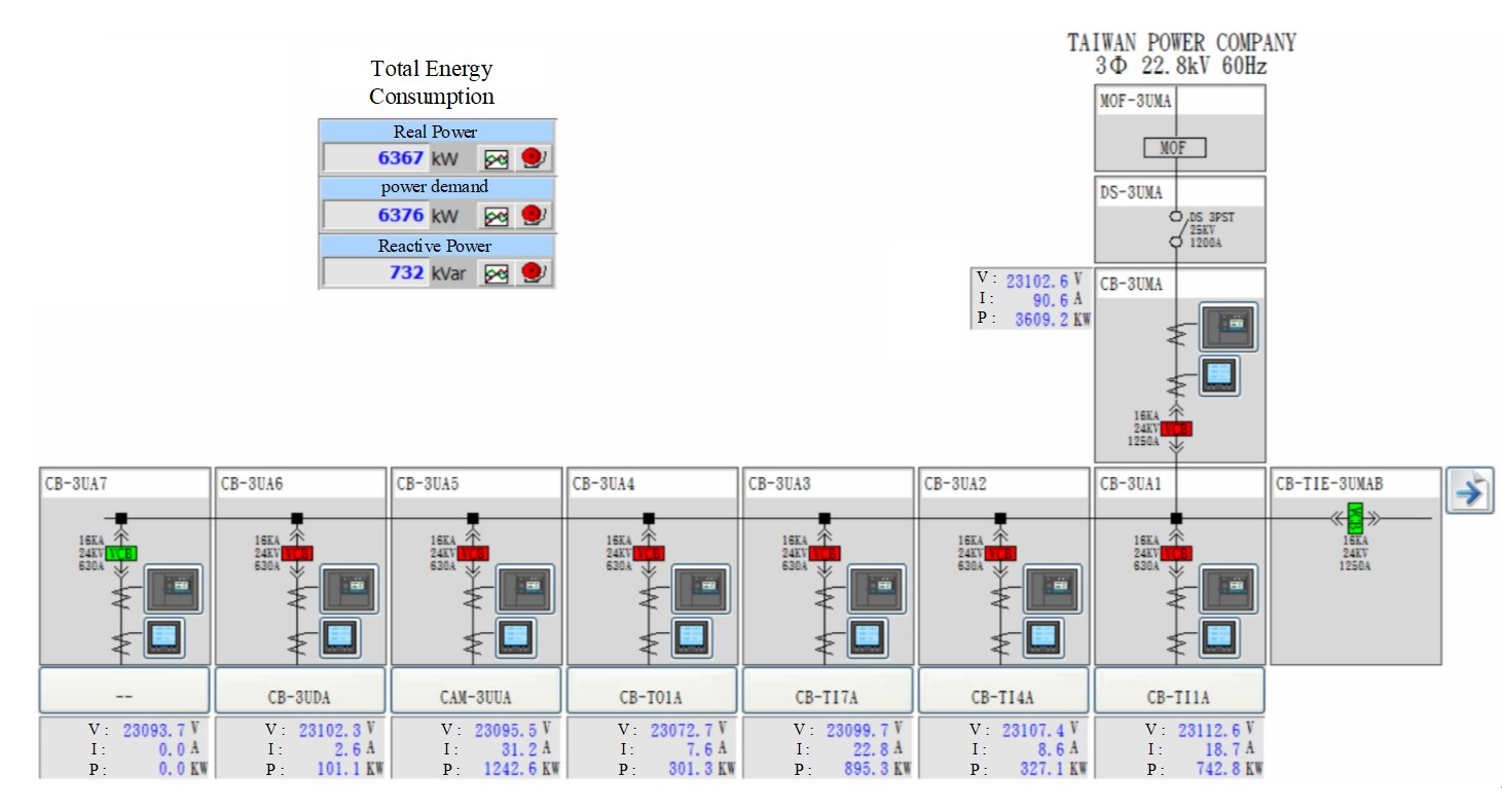
Figure 11: The main page of GUI of power SCADA
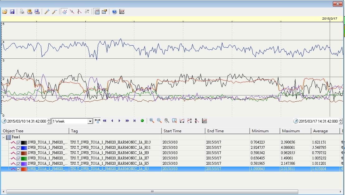
Figure 12: The harmonic trend charts.
The real time power quality monitoring system
For monitoring effectively the real time status of NSRRC’s electric power system, an electric power quality monitoring system has been set up to measure the power quality of high voltage feeders, which includes the voltage/current phase, the variation of frequency, voltage sags and swells. The measured result will be analyzed and used to further improve the performance of power system. Furthermore, a partial discharge monitoring system was also installed to monitor the phenomena of electric discharges.
Figure 13: The real time phasor diagram and power parameters at TPS.
Design and measurement of the grounding System
The grounding system is crucial to the safety issues, the electrical reference level, the electrical noises and EMI problems. In order to have a higher grade of power quality and to reduce the electrical noise interference among equipments, the ground grid system of TLS was improved in 2002 by adding nine 30 m long ground vertical electrodes, Fig. 14. This reduced the TLS ground resistance to about 0.2 Ω. For the TPS grounding system, the ground grid was also designed to have a resistance smaller than 0.2 Ω. After the completion of the grid, the measured ground resistance is lower than 0.14 Ω,Fig. 14.
Figure 14: grounding system.
Exhaust Gas Treatment System
The acid/alkaline gas stream is removed with scrubber, Fig. 15. The scrubber is designed to have 100% handling capacity. Also, the organic exhaust is handled and removed with active charcoal. At present, both systems operate with only 50% capacity. They could be increased in the future depending on its needs.
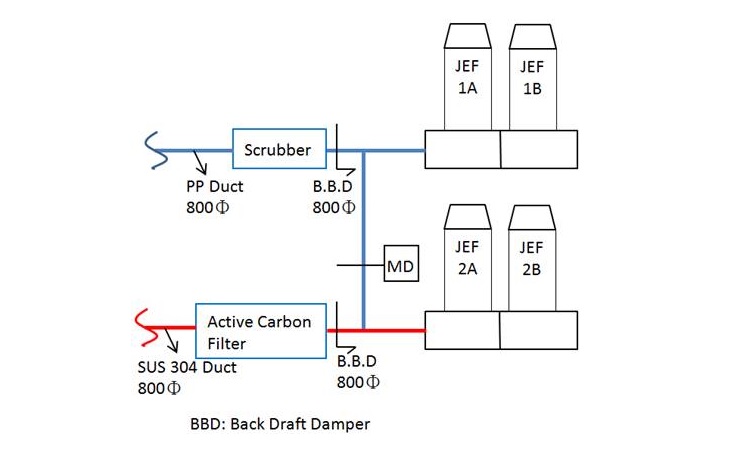
Figure 15: The acid/alkaline gas stream handling system.
Fire Protection System
The buildings of NSRRC are distributed over a slightly large area. A partial of TPS building is also located underground. Many valuable equipment and devices are installed inside these buildings. A thoroughly designed fire protection system has been installed, which consists the alarm system, the fire extinguish system and the evacuation system.
Alarm system
Due to the buildings of NSRRC located in extended area, a fire alarm system adopted an R-type (recordable type) which is addressable with graphic user interface. In case of fire, this system is able to reduce the response time, increase the fire extinguishing success rate, and allow personnel to escape to safe place quickly. At the same time, the fire alarm system will be interlocked with the emergency broadcast system, the smoke exhaust system, etc. and lift the access control of doors in the evacuation routes for people to escape quickly.
Fire extinguishing system
Beside the manual type fire hydrants installed around indoor and outdoor, automatic sprinkler systems were also installed in TLS buildings, foam based hydrants were installed in underground parking lot in Activity Center. Also, the automatic gaseous fire suppression devices were installed in some power facilities having higher risk of fire.
Evacuation system
The evacuation system consists of evacuation direction lights, exit lights and emergency lights. Because partial of the building is underground, the smoke extraction equipments are installed in these areas in order to give more time for people to escape.
Civil Affair and Building
Construction planning and management
Our group is also responsible for the life cycle works of civil, building and interior construction project which includes planning, procurement, construction and maintenance. The main aim is to ensure the quality of the civil engineering work, so it can meet the requirement demanded by the high grade laboratory.
In the design and construction phase the 3D model or BIM technologies has been used to check the constructability, Fig. 16 and Fig. 17. This approach can help to eliminate the unnecessary cost and time waste caused by rework due to mistakes. The BIM can also be used to analyze the space usage and interior design functions. It is to ensure the construction project be completed flawlessly. So, the people at NSRRC can have a comfortable environment to work and to perform excellent advanced researches.
Figure 16: 3D model application in space conflict and constructability analysis
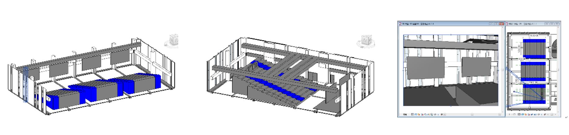
Figure 17: Usage analysis of conference room arrangement
Maintenance and renovation
Besides the new construction work, other important tasks of our group are maintenance and renovation. These works include the annual building public safety inspection and report, renovation of building and civil works, maintenance of sanitary and drain system, domestic water heating system maintenance and other general repair works. With the accomplishment of these works, it will provide a safety and comfortable environment for users.
Photovoltaic system
In order to support the Taiwan Green Energy Policies about energy saving and carbon reduction, NSRRC has constructed a Green Power Generation System. The Photovoltaic (PV) system has been built on the roof of several buildings at NSRRC site, Fig. 18, Fig. 19 and Fig. 20. This rooftop PV system is helpful in saving air conditioning consumption because it can reduce the direct sunlight and lower the building interior temperature. Besides, it can also reduce the damage of waterproof materials in the roof caused by solarization and cut down the repair works and expenses. Moreover, the energy generated by the photovoltaic system can be delivered to the Taiwan Power Company to earn a financial benefit. A data collection platform for this photovoltaic system has also been set up to monitor the PV energy generation and its related information. The acquired data can be analyzed to further improve the solar energy supply system of NSRRC.
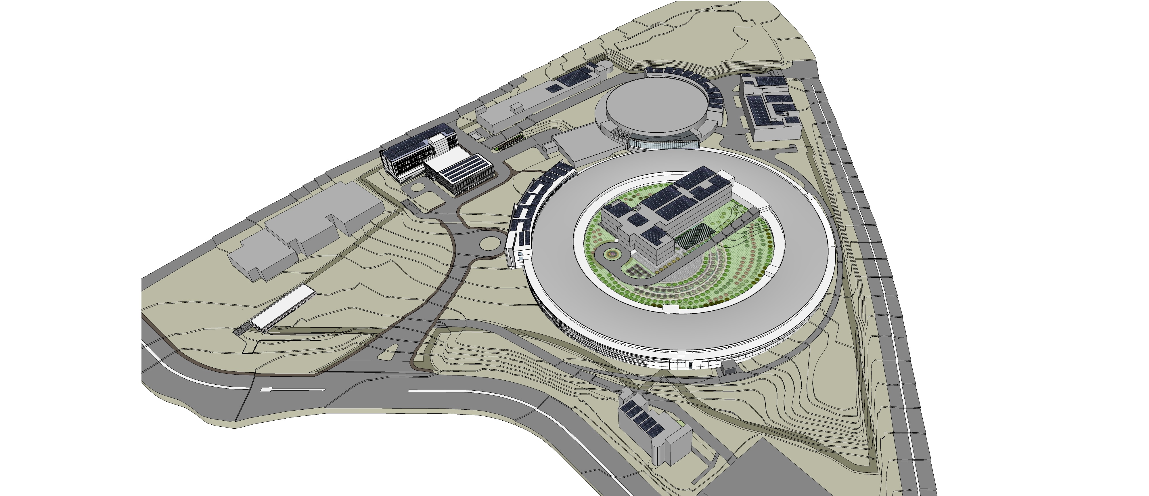
Figure 18: The planning of PV system in NSRRC

Figure 19: The scale plan of PV system