SRF modules for TPS
The SRF cavity has two features: (1) high accelerating voltage and high power in comparison with the traditional copper cavity and (2) large beam chamber so that the ferrite dampers on beam tubes of both sides of the SRF cavity can adsorb the EM waves of higher order modes. Because of these features, SRF cavities can provide more power to the particle beam with better stability through decreasing the couple bunch instability. Many 3rd generation synchrotron light facilities, like the TLS and TPS (in Taiwan), DLS (in Britain), CLS (in Canada), SSRF (in China), PLS II (in Korea), and NSLS II (in USA), all select the SRF modules as the accelerating cavity.
Two 500-MHz SRF modules of KEKB-type are currently installed in TPS accelerator as the main accelerating cavities, while another identical SRF module is stored in RF lab as the spare. These modules are developed by KEK, Japan. All components are manufactured and partly assembled by Mitsubishi Heavy Industry (MHI) in Japan. After surface treatment on cavities and couplers and performance examination in KEK, all the components and sub-assemblies are transported to NSRRC. With the technique transfer and advisory from KEK, the final assembly in clean room is operated by NSRRC staffs in NSRRC. The final high power tests on these SRF modules are also performed in NSRRC and show great RF performance. The key SRF technique and maintenance are thus established. In 2015, TPS achieves the design goal of 500-mA operation with bare lattice by two SRF modules.
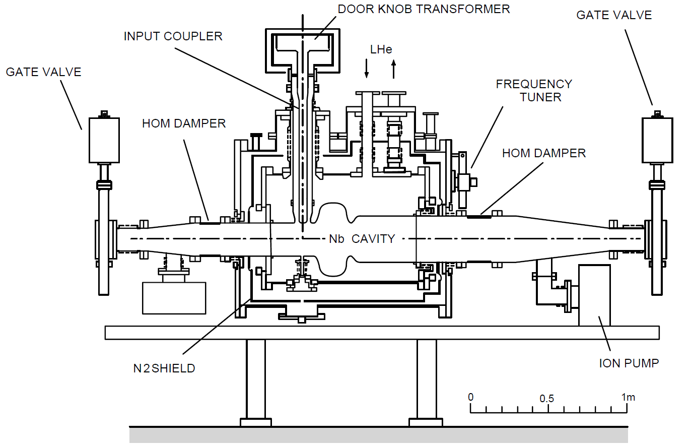
Fig 1. Sketch of the KEKB-type 500-MHz SRF module.

Fig. 2 The SRF module for the electron storage ring of TPS.
Table I. Main Specifications
| Operation frequency |
499.650 MHz |
| Q0 @ 1600 kV |
> 1.0e9 |
| Tunable range of Qext |
6.0e4 to 1.2e5 |
| Static heat loss of LHe vessel at 4.5 K |
< 35 W |
| RF power rating of cavity |
300 kW-CW / set |
| Maximal cavity accelerating voltage |
> 2.0 MV / set |
| Vacuum |
Cavity / Thermal Insulation vacuum |
| (at liquid-helium temperature) |
|
|
| Leak rate |
| (1) Cavity to ambient |
| (2) Cavity to helium vessel |
| (3) Helium vessel to insulation vacuum |
| (4) Insulation vacuum to ambient |
|
| |
| <2.0e-9 mbar l/ sec |
| <2.0e-9 mbar l/sec |
| <2.0e-8 mbar l/sec |
| <2.0e-8 mbar l/sec |
|
Valve Box and the Related Control
The SRF modules are installed inside a liquid helium vessel to achieve an operation temperature around 4.5 K. A cold box with a capacity of 890 W at refrigeration mode, or 269 liter/h at liquefaction mode, generates the liquid helium into a main Dewar of 7000-liter. As shown in Figure 3, the liquid helium is then delivered to the distribution valve box (DVB) and SRF valve boxes (VB#1 ~ VB#4) through multi-channel lines, and finally to the SRF modules with the vaporized cold helium goes back to the cold box as a counter flow to raise the refrigeration efficiency. The valves on the DVB and SRF valve boxes controls not only the liquid helium flow rate to maintain the liquid level inside the liquid helium vessel of the SRF module, but also the cold return gas flow to stabilize the vessel pressure. Meanwhile the liquid nitrogen shields all the cold helium lines of the multi-channel lines and valve boxes, as well as the liquid helium vessel of the SRF modules, to reduce the static thermal load to the cold helium. An outdoor 60-m3 Dewar is the source of the liquid nitrogen, while a 1000-liter phase separator is located near the main LHe Dewar to guarantee stable supply pressure and pure liquid nitrogen to DVB. The flow rate to each SRF module is controlled by the valves on corresponding SRF valve box. The vaporized nitrogen goes back to DVB as a counter flow and then vented to air through a passive warmer.
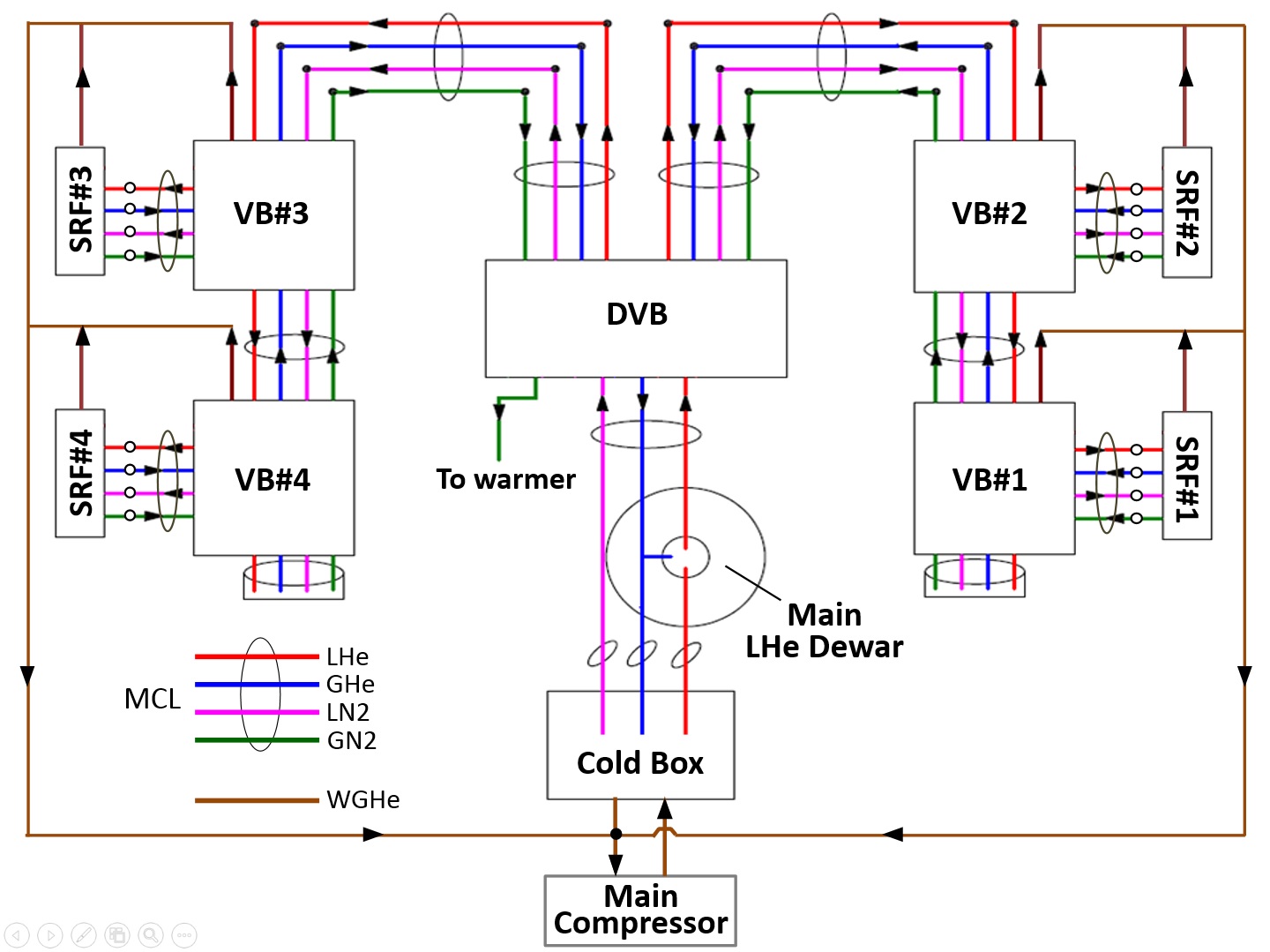
Fig. 3 Distribution of the cryogenic fluids for SRF modules.
TPS RF Transmitter
The RF transmitter generates the RF power to provide energy to the stored particle in accelerator. As illustrated in the figure, the low-level RF control system detects and computes some signals from the SRF cavity and sends a signal to drive the pre-amplifier of the RF transmitter, accordingly the RF transmitter generates the proper power to feed to SRF cavity, through RF transport lines (waveguide) and protection units (circulator and RF load). Each RF transmitter of TPS consists a 55kV/12A DC high-voltage power supply and a 300 kW klystron, as well as programmable logic controller (PLC) and FPGA-based interlock control system (ICS). Auxiliaries such as power supplies, cooling water and air are also integrated. Currently, two set of 300kW and one set of 100 kW transmitter systems are installed for the routine operation in the TPS storage ring and booster ring, respectively.
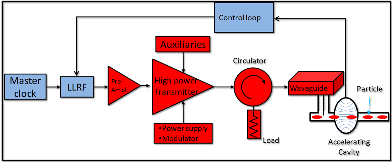
Fig. 4 Typical layout of the RF system.
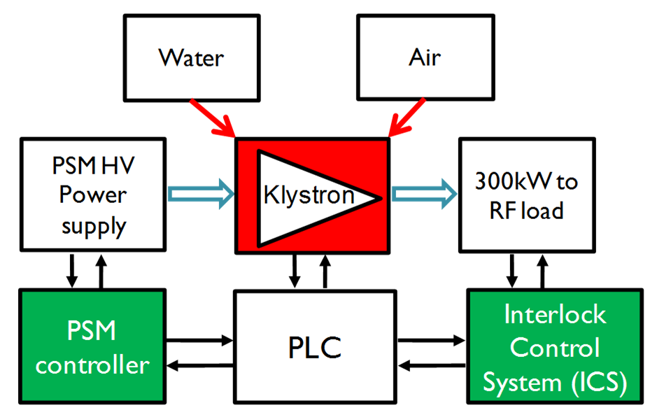
Fig. 5 Block diagram of the RF transmitter.
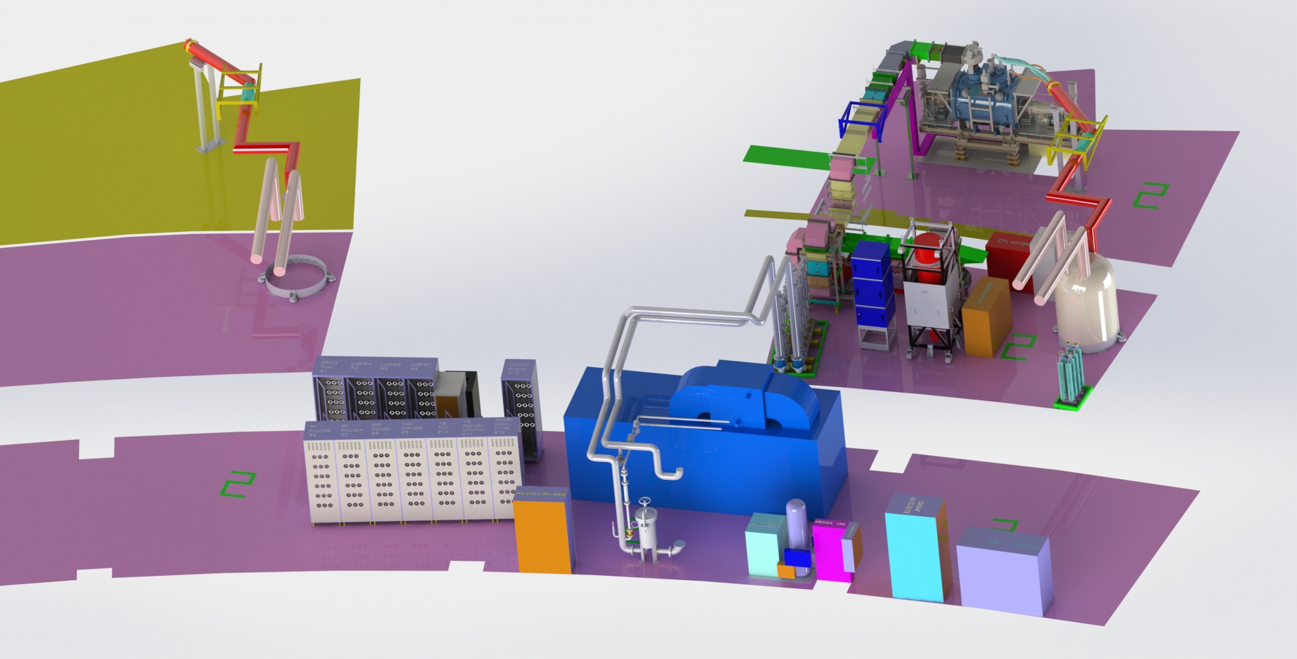
Fig. 6 Layout of the RF system for TPS storage ring.
TPS SSPA
A solid-state power amplifier (SSPA) is a kind of power amplifier including a power chip made of semiconductor integrated circuits as the core, resonance circuits to generate radio frequency (RF), and matching circuits to decrease reflection. By stacking multiple SSPA modules, the power can range from tens of watts to hundreds of kilowatts. Thus, the SSPA has a wide range of applications such as radar, wireless communications, microwave home appliances, medical equipment, and automotive devices. Comparing with a traditional klystron amplifier, the SSPA has a few outstanding advantages, such as no need of a high voltage source, a better reliability due to stacking redundant modules, a faster repair by directly replacing the fault module, and low-cost manufacturing. The SSPA module is designed and manufactured by NSRRC as the RF source for an electron accelerator at Taiwan Photon Source (TPS). The pictures of SSPA are shown as Fig.7 including Fig.7(a) a 80 kW Power Tower, Fig.7(b) a single module, and Fig.7(c) a power chip. The colleagues of RF group are going to achieve the goal of establishing a 320 kW SSPA.
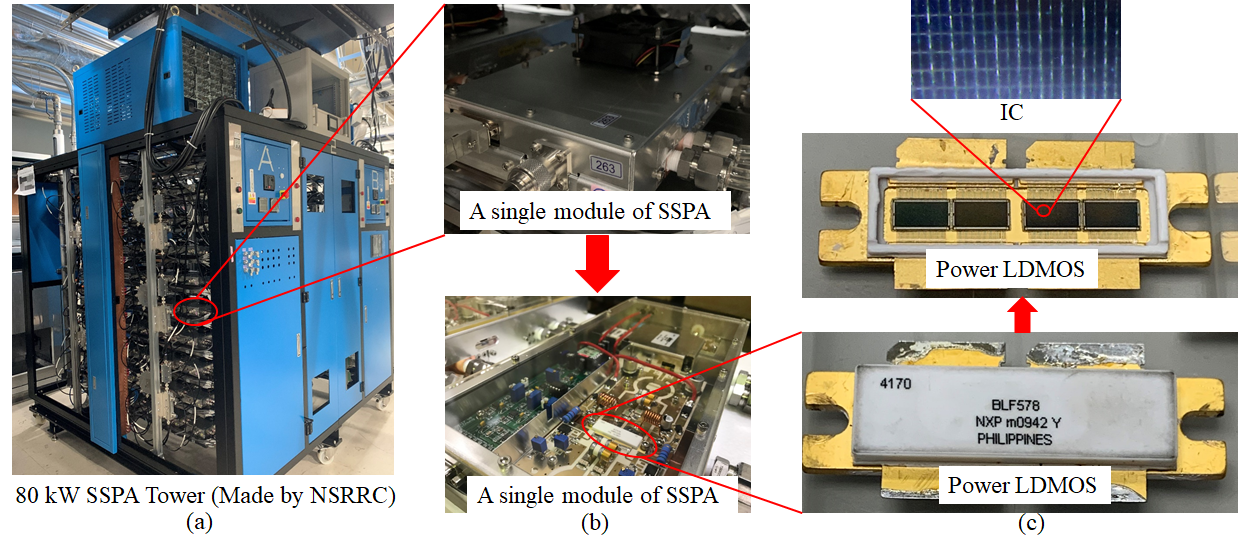
Fig. 7 SSPA (a) a 80 kW Power Tower, Fig.7(b) a single module, and Fig.7(c) a power chip.
Low-Level RF Control System
Any a fluctuation of the RF parameters, such as pressure of the SRF helium vessel and the working conditions of klystron, could disturb the phase and amplitude of the accelerating field inside the SRF cavity. Illustrated in the Fig. 8 are the three main control loops of the low-level RF control system to compensate the external disturbances. The amplitude loop controls the gap voltage by comparing the transmitted power and the setting; the phase loop adjusts the phase shifter by comparing the phase error between the transmitter power and the master clock to feed the RF power to SRF cavity with proper phase; and the tuner loop adjusts the cavity’s resonance frequency through driving stepping motor of the mechanical tuner by comparing the phase error between the forward power and the transmitter power. Besides these three control loops, the interlock system and the diagnosing system are also implemented to the LLRF for RF system securing and debugging.
Due to small momentum compaction factor, the synchrotron oscillation frequency of TPS is low as 3 kHz. Bandwidth of each control loop of the LLRF can not fall near this frequency. Currently the bandwidth of amplitude loop and phase loop is 600 Hz and 2.2 kHz, respectively. To reduce the noise disturbances from the 60-Hz power line, the digital LLRF is soon to be implemented.
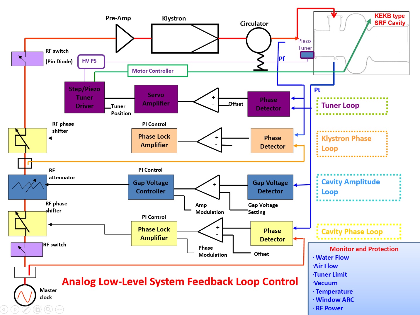
Fig. 8 Layout of the TPS analog LLRF system.
Members of RF Group